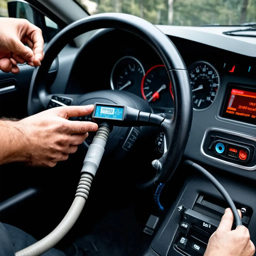
The VCDS (VAG-COM Diagnostic System), a powerful software tool used with a compatible interface cable, allows you to delve deep into the electronic control units (ECUs) of your Volkswagen, Audi, Seat, Skoda, and even Bentley vehicle. This article focuses on a crucial aspect of using VCDS: understanding the VCDS pinout. Knowing your cable’s pinout is essential for troubleshooting communication issues, modifying your cable for specialized tasks, or even building your own custom cable.
Demystifying the VCDS Pinout
Simply put, the “pinout” refers to the specific arrangement and function assigned to each pin within the OBD-II connector of your VCDS cable. This connector, a standard feature in most modern vehicles, serves as the gateway for communication between your vehicle’s ECUs and the VCDS software.
“Understanding the pinout is like knowing which wires carry which signals,” says John Miller, an automotive electronics specialist and author of “Unlocking Your Car’s Brain.” “This knowledge becomes invaluable when troubleshooting connectivity problems or wanting to expand your diagnostic capabilities.”
Why Knowing Your VCDS Pinout Matters
- Troubleshooting: A frequent issue encountered by VCDS users is communication failure with the vehicle. By knowing your cable’s pinout, you can use a multimeter to test for continuity, shorts, or open circuits within the cable itself, potentially identifying the culprit behind connection problems. Refer to resources like https://cardiagtech.com/vcds-no-response-from-controller/ for guidance on troubleshooting VCDS communication issues.
- Cable Modification: For advanced users, the ability to modify your VCDS cable opens doors to specialized functionalities. For instance, you can add a switch to access K-Line communication on older vehicles or connect specific pins to LEDs for visual diagnostic feedback.
- DIY Cable Building: While not recommended for beginners, technically inclined individuals with a good understanding of electronics can use pinout information to create their custom VCDS cables tailored to their specific needs.
Common VCDS Pinout Configurations
While several VCDS cable versions exist, the most prevalent pinout configurations are for the standard OBD-II connector, which consists of 16 pins. The table below illustrates a typical VCDS pinout:
| Pin Number | Signal Name | Description |
|---|---|---|
| 2 | J1850 Bus+ | Used for communication on some Ford vehicles |
| 4 | Chassis Ground | Ground connection for the vehicle chassis |
| 5 | Signal Ground | Ground connection for signal circuits |
| 6 | CAN High (CAN H) | High-speed CAN bus communication line |
| 7 | K-Line | Communication line for older vehicles (ISO 9141) |
| 14 | CAN Low (CAN L) | Low-speed CAN bus communication line |
| 16 | Battery Voltage | Provides power to the diagnostic interface |
Note: This is just a general representation, and the actual pinout of your specific VCDS cable might vary slightly. Always refer to the documentation provided by your cable manufacturer for the most accurate information.
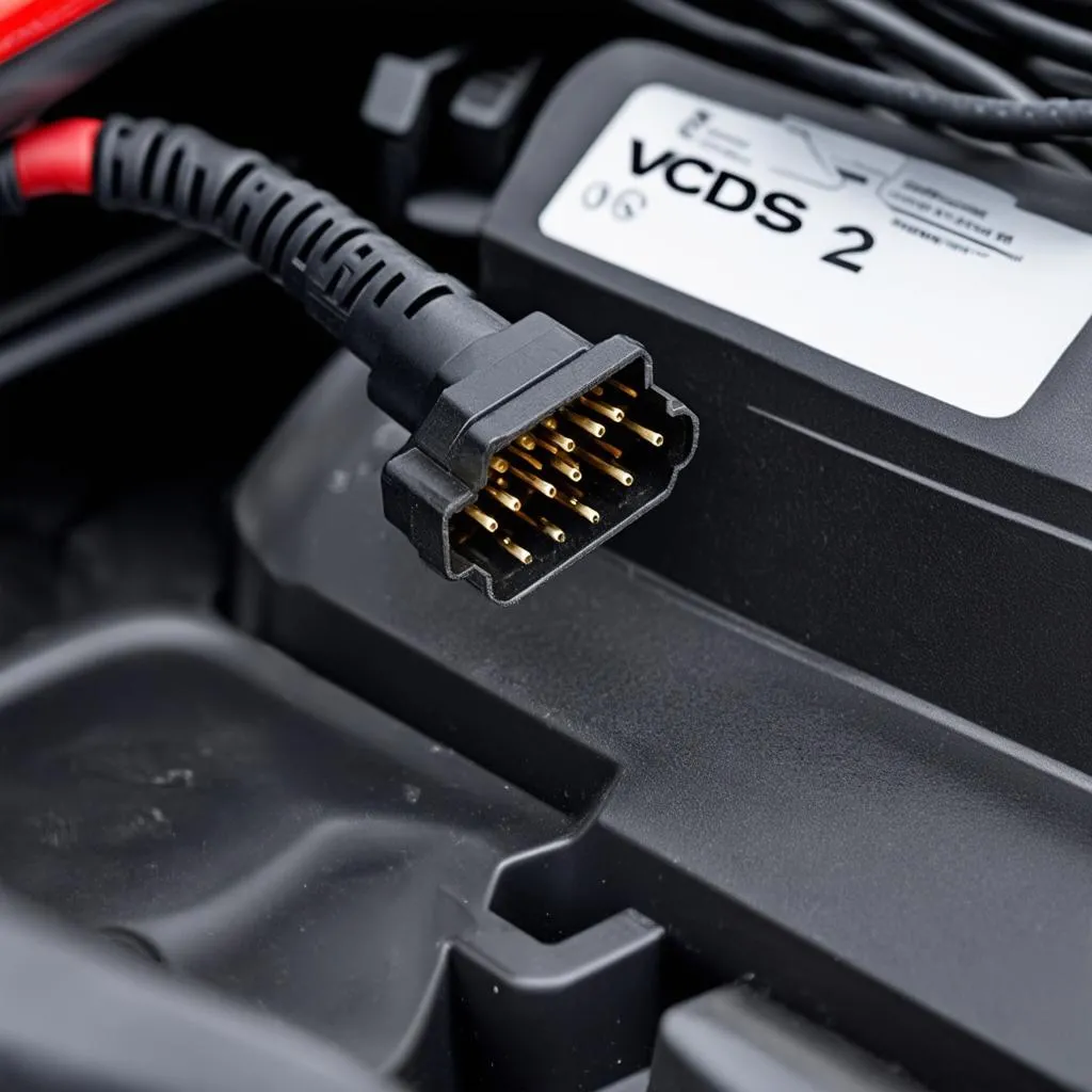 VCDS Cable OBD2 Connector
Finding Your Cable’s Pinout
- Consult the Manufacturer: The most reliable way to determine your cable’s pinout is to refer to the documentation that came with your VCDS interface. This information might also be available on the manufacturer’s website.
- Visual Inspection: Some cables might have the pinout information printed directly on the connector housing. Examine your cable closely to see if this information is available.
- Online Resources: Various online forums and communities dedicated to automotive diagnostics and VCDS often have pinout diagrams and information shared by users. However, exercise caution when using such resources, ensuring the information’s credibility before relying on it.
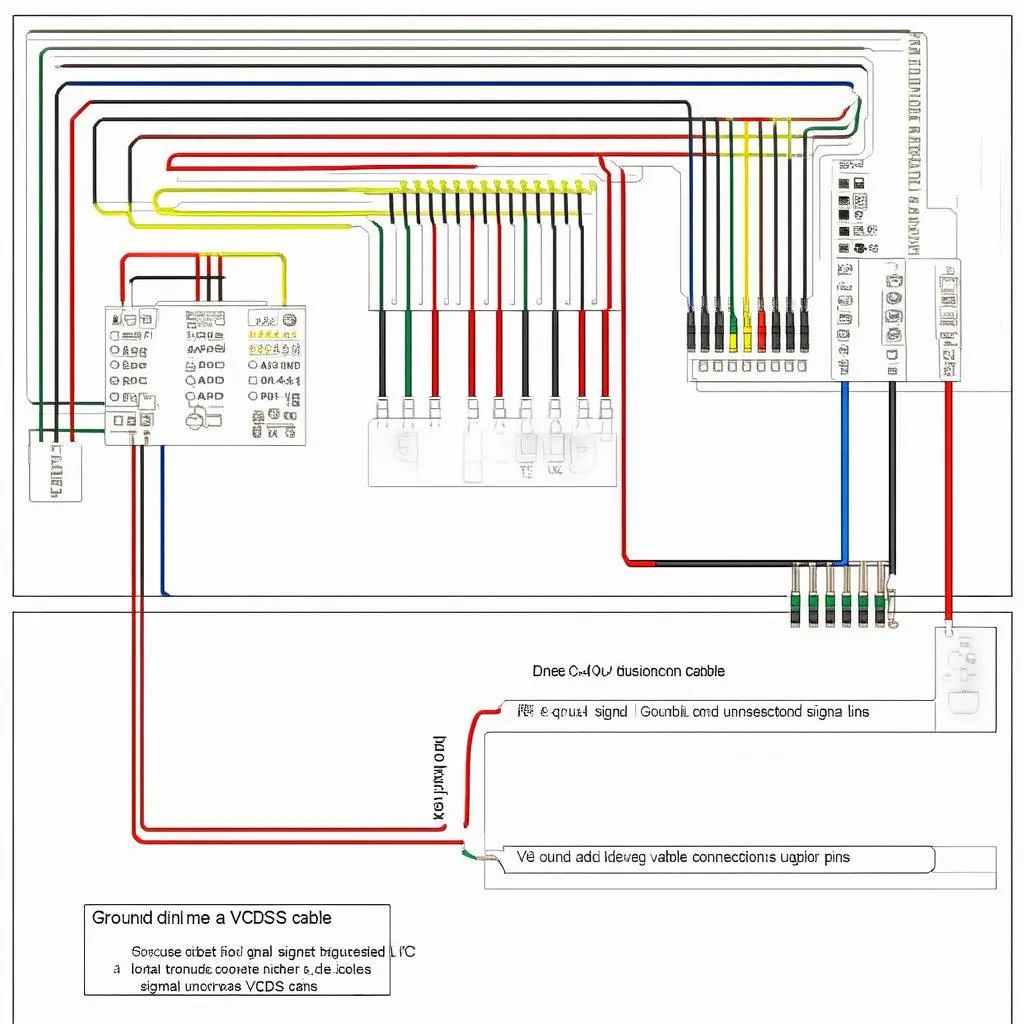 VCDS Pinout Diagram
FAQs about VCDS Pinouts
Q: Can I damage my vehicle by incorrectly connecting the VCDS cable?
A: While the OBD-II port is designed to be relatively foolproof, connecting the cable incorrectly can potentially damage the cable or the vehicle’s electronics. Always double-check the pinout and ensure the connector is correctly aligned before plugging it in.
Q: Do I need to understand the pinout if I’m only using VCDS for basic diagnostics?
A: While understanding the pinout isn’t mandatory for basic tasks, it can be helpful for troubleshooting communication issues or if you encounter error messages related to specific communication lines.
Conclusion
Understanding the VCDS pinout empowers you to maximize the capabilities of your diagnostic tool. Whether you’re a seasoned professional or a DIY enthusiast, this knowledge can be invaluable for troubleshooting, modifications, and expanding your diagnostic skills. Remember to prioritize safety, consult reliable sources for information, and always double-check your connections before powering up your VCDS system. For further assistance or more in-depth technical guidance, consider reaching out to the experts at CARDIAGTECH for comprehensive support on all your automotive diagnostic needs.