Understanding pulse width modulation (PWM) signals is crucial for effective vehicle diagnostics using VCDS (Vag-Com Diagnostic System). This article provides a comprehensive guide on how to interpret these signals, empowering car owners, repair shop owners, and technicians to diagnose and resolve vehicle issues efficiently. We’ll cover the basics of PWM, how it relates to VCDS readings, and how you can leverage this knowledge for advanced troubleshooting.
What is Pulse Width Modulation (PWM)?
Pulse width modulation is a technique used to control analog devices with digital signals. It works by rapidly switching a digital signal between on and off states. The duration of the “on” time, known as the pulse width, determines the effective power delivered to the component. A longer pulse width delivers more power, while a shorter pulse width delivers less. This allows for precise control over various vehicle functions, including fuel injectors, solenoids, and actuators.
How Does VCDS Display PWM Signals?
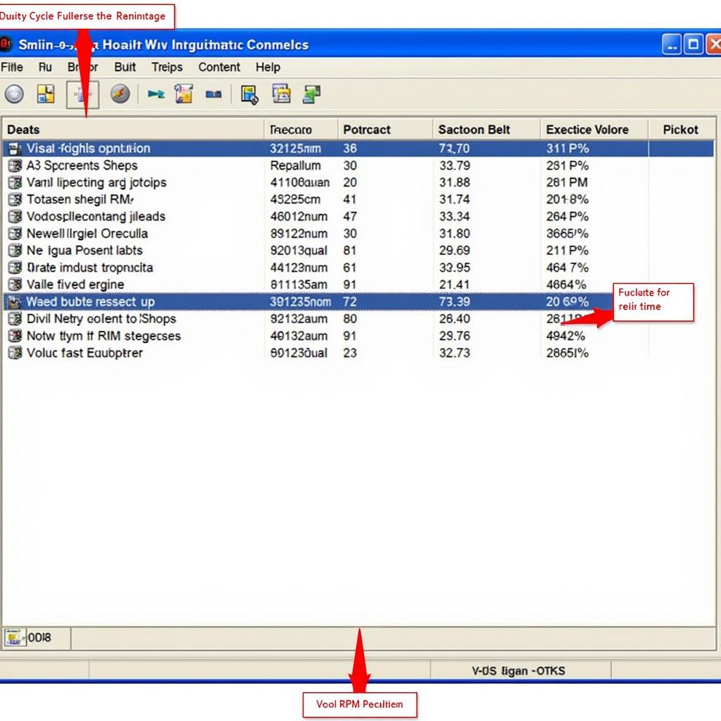
VCDS displays PWM signals as a percentage, often referred to as the “duty cycle.” This duty cycle represents the percentage of time the signal is in the “on” state within a given period. For example, a 50% duty cycle means the signal is “on” for half the period and “off” for the other half. A 10% duty cycle indicates the signal is “on” for only 10% of the period.
 VCDS PWM Display Example
Understanding this percentage allows you to assess the behavior of the controlled component. A faulty component might exhibit unusual duty cycle fluctuations or remain stuck at a specific value, indicating a problem.
Understanding Duty Cycle and its Impact on Component Behavior
The duty cycle directly affects how a component functions. For instance, in a fuel injector, a higher duty cycle translates to a longer injection duration, delivering more fuel. In an EGR (Exhaust Gas Recirculation) valve, a higher duty cycle means the valve is open for a longer period, allowing more exhaust gas to recirculate. Analyzing the duty cycle in relation to the expected behavior of the component is key to accurate diagnostics.
Common Issues Revealed by VCDS Pulse Width Readings
Incorrect PWM signals can indicate a variety of issues, such as faulty wiring, failing components, or software glitches. For example, a consistently low duty cycle to a fuel injector might suggest a wiring problem, while a fluctuating duty cycle might indicate a failing sensor. Recognizing these patterns is essential for effective troubleshooting.
Practical Examples of Reading VCDS Pulse Width
Let’s consider a few practical scenarios:
-
Scenario 1: Intermittent Misfire: If you’re experiencing an intermittent misfire, monitoring the injector pulse width for each cylinder can help identify the culprit. A significantly lower duty cycle on one cylinder compared to the others might indicate a problem with that specific injector or its wiring.
-
Scenario 2: EGR Valve Issues: A stuck EGR valve can cause performance problems. By monitoring the EGR valve’s duty cycle, you can determine if the valve is operating correctly. A constant 0% or 100% duty cycle could indicate a stuck valve.
-
Scenario 3: N75 Valve Troubleshooting: The N75 valve controls turbocharger boost pressure. Observing its duty cycle can reveal issues related to boost control. A constantly high duty cycle might suggest a boost leak.
Advanced Troubleshooting Tips using VCDS Pulse Width
For more advanced diagnostics, you can compare the actual PWM signal against the expected value based on operating conditions. This requires access to the vehicle’s technical documentation. Discrepancies between the actual and expected values can pinpoint the source of the problem. You can also log the PWM signal over time to identify intermittent issues.
Conclusion
Understanding how to read and interpret VCDS pulse width readings is essential for effective vehicle diagnostics. By mastering this skill, you can accurately diagnose a wide range of vehicle issues and perform targeted repairs. Remember to always consult the vehicle’s technical documentation for specific information related to PWM signals and their expected values. This comprehensive approach empowers you to tackle complex automotive problems with confidence.
FAQ
- What does a 0% duty cycle mean? A 0% duty cycle indicates the signal is constantly “off.”
- What does a 100% duty cycle mean? A 100% duty cycle indicates the signal is constantly “on.”
- Can I use VCDS to control PWM signals? VCDS primarily allows for monitoring, not controlling, PWM signals.
- What are some common causes of PWM signal issues? Faulty wiring, failing components, and software glitches are common causes.
- Where can I find more information about VCDS pulse width readings? Consult your vehicle’s technical documentation and online forums dedicated to VCDS.
- How often should I check PWM signals? Regular monitoring during routine maintenance can help identify potential problems early.
- What other data can I analyze alongside PWM signals for a more comprehensive diagnosis? Other relevant data includes sensor readings, error codes, and live data from other control modules.
For further guidance on VCDS procedures, check out our articles on vw dpf regeneration procedure vcds and vcds lambda test.
When you need assistance, contact us via WhatsApp: +1 (641) 206-8880, Email: CARDIAGTECH[email protected] or visit our workshop at 276 Reock St, City of Orange, NJ 07050, United States. Our customer support team is available 24/7.


