A brake warning light on your dashboard is a crucial safety feature, alerting you to potential issues with your vehicle’s braking system. This warning light is connected to a complex network of components, all working together to ensure your ability to slow down and stop safely. At the heart of this system lies the brake warning circuit diagram, a roadmap of sorts that outlines the electrical pathways and connections within your braking system. Understanding this diagram can be invaluable, especially when troubleshooting problems or performing maintenance.
Decoding the Diagram: A Step-by-Step Guide
 Brake Warning Light Circuit Diagram Basics
While the specifics might vary depending on the make and model of your car, most brake warning circuit diagrams follow a similar logic. Here’s a step-by-step breakdown to help you decipher yours:
- Identify the Power Source: The diagram will typically begin with the battery, the primary power source for your vehicle’s electrical system.
- Trace the Path to the Ignition Switch: From the battery, the circuit will lead to the ignition switch. This ensures that the brake warning light circuit only becomes active when the vehicle’s ignition is turned on.
- Locate the Brake Light Switch: This crucial component, usually located near the brake pedal, is responsible for detecting when the brake pedal is depressed.
- Follow the Circuit to the Warning Light: The diagram will show how the circuit connects the brake light switch to the brake warning light on your dashboard. When the brake pedal is pressed, the switch closes the circuit, allowing current to flow to the warning light and illuminate it.
- Identify the Ground Connection: Finally, the circuit diagram will show the path back to the ground, completing the electrical loop.
Common Issues and Troubleshooting Tips
Understanding the brake warning circuit diagram can be incredibly helpful when diagnosing problems. Here are some common issues and troubleshooting tips:
- Brake Warning Light Stays On: This could indicate a few things:
- Worn Brake Pads: Most vehicles have sensors that trigger the warning light when brake pads wear thin.
- Low Brake Fluid: A drop in brake fluid level can trigger the warning light. Check the brake fluid reservoir and top it up if necessary.
- Faulty Brake Light Switch: A malfunctioning switch might send a continuous signal, keeping the light on.
- Electrical Short: A short circuit in the wiring can also cause the light to stay illuminated.
- Brake Warning Light Doesn’t Come On: If the light fails to illuminate when the brake pedal is pressed, this could point to:
- Burned Out Bulb: Just like any other bulb, the brake warning light bulb can burn out. Check and replace if needed.
- Faulty Brake Light Switch: A faulty switch might not close the circuit, preventing the light from turning on.
- Wiring Issue: A break or damage in the wiring can interrupt the flow of current to the light.
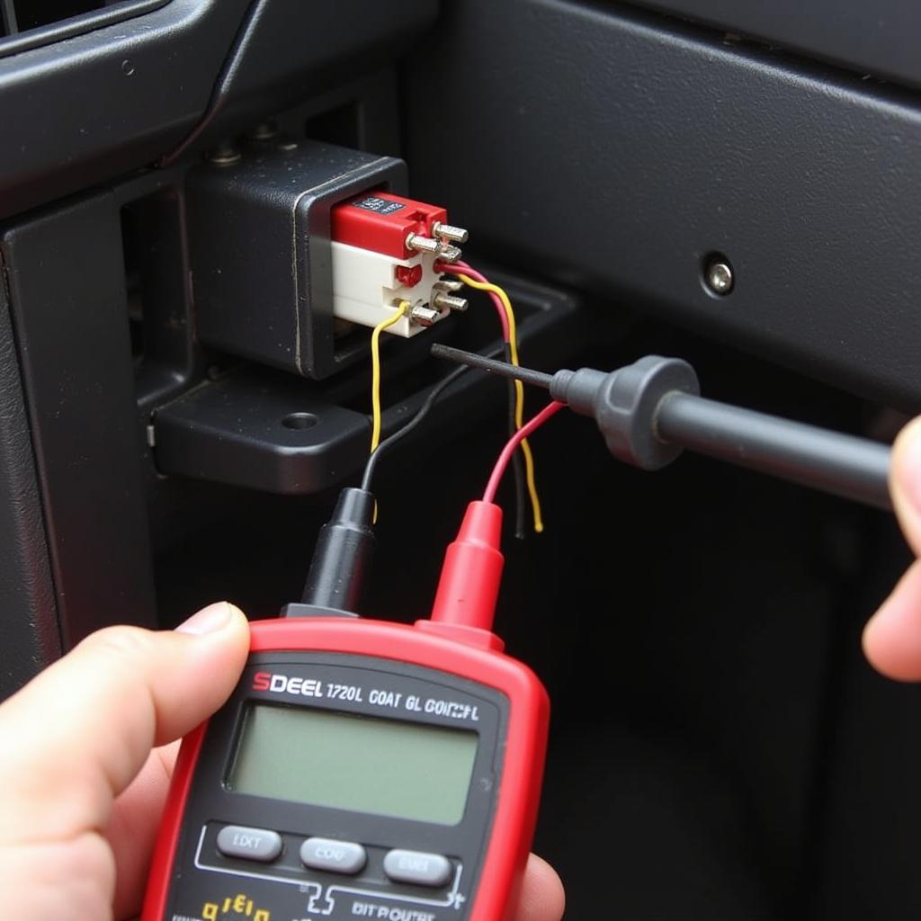 Testing a Brake Light Switch with a Multimeter
The Importance of Professional Diagnostics
While understanding the brake warning circuit diagram can provide you with a good starting point for troubleshooting, it’s crucial to remember that modern vehicles have complex electrical systems.
“Attempting to diagnose and repair brake system issues without proper knowledge and tools can be dangerous,” says automotive electrical engineer, Dr. Emily Carter. “It’s always recommended to consult with a qualified mechanic, especially when dealing with critical safety systems like your brakes.”
Beyond the Basics: Advanced Features
Modern vehicles often incorporate advanced features into their braking systems, such as:
- Anti-lock Braking System (ABS): This system prevents wheel lockup during hard braking, improving vehicle control.
- Electronic Brake-force Distribution (EBD): EBD optimizes braking force distribution between the front and rear wheels, enhancing stability.
- Brake Assist: This feature provides maximum braking force in emergency situations, even if the driver doesn’t apply enough pressure to the brake pedal.
These advanced systems add complexity to the brake warning circuit, often incorporating additional sensors, control modules, and wiring harnesses.
Conclusion
The brake warning circuit diagram is your guide to understanding the electrical pathways that keep you safe on the road. While a basic understanding can help you with initial troubleshooting, remember that professional diagnostics are crucial for ensuring the proper functioning of your vehicle’s braking system. Don’t hesitate to seek expert help when needed – your safety is paramount.
FAQs
- Can I drive my car if the brake warning light is on? It’s strongly advised against driving with the brake warning light illuminated. This indicates a potential issue with your braking system that could compromise your safety.
- How often should I check my brake fluid? It’s a good practice to check your brake fluid level at least once a month.
- How much does it cost to replace a brake light switch? The cost can vary depending on the make and model of your car, but it’s typically a relatively inexpensive repair.
- Where can I find a brake warning circuit diagram for my specific car model? Your vehicle’s service manual is the best resource for this information. You might also be able to find diagrams online.
- Do I need special tools to troubleshoot brake warning light issues? A digital multimeter is a helpful tool for testing electrical components within the circuit. However, it’s important to know how to use it safely and correctly.