Understanding your JVC car radio wiring diagram is crucial for a successful installation. Whether you’re upgrading your car audio system or troubleshooting a malfunctioning radio, a clear grasp of the wiring diagram interface (DI) is essential. This guide will provide you with a comprehensive overview of JVC car radio wiring DI, empowering you to navigate the complexities and achieve optimal audio performance.
Decoding the JVC Car Radio Wiring DI
The JVC car radio wiring DI serves as a roadmap, illustrating the connections between the radio unit and your vehicle’s electrical system. It’s a visual representation of how each wire should be connected for proper functionality. Ignoring this crucial information can lead to blown fuses, damaged components, or a non-functioning radio. Therefore, familiarizing yourself with the DI is the first step towards a successful installation or repair.
Power, Ground, and Illumination: The Foundation of Your JVC Car Radio
The primary connections involve power, ground, and illumination. The constant 12V power wire (usually yellow) provides continuous power to the radio, maintaining memory functions like presets and clock settings. The ignition-switched 12V power wire (typically red) only supplies power when the ignition is on, powering the radio’s main functions. The ground wire (black) completes the circuit, ensuring electrical stability. Lastly, the illumination wire (usually orange/white) dims the radio display along with your vehicle’s dashboard lights.
Speaker Wiring: Bringing Your Music to Life
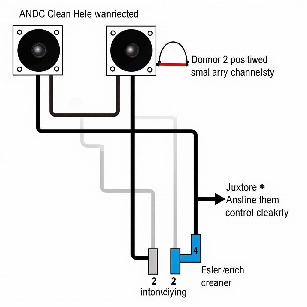
Connecting the speakers correctly is paramount for optimal sound quality. The JVC car radio wiring DI clearly labels the positive (+) and negative (-) wires for each speaker channel (front left, front right, rear left, and rear right). Matching the polarity of the wires is essential to prevent phase cancellation and ensure proper sound reproduction. Using high-quality speaker wire and ensuring secure connections will further enhance the audio experience.
Antenna and Amplifier Connections: Enhancing the Signal and Power
The antenna wire supplies the radio with the signal necessary for receiving radio broadcasts. Properly connecting this wire ensures clear reception. If your JVC car radio includes an amplifier, the DI will indicate the dedicated power control wire (usually blue/white). This wire activates the amplifier when the radio is turned on, boosting the audio output.
 JVC Car Radio Speaker, Antenna, and Amplifier Connections
Troubleshooting Common JVC Car Radio Wiring DI Issues
While the JVC car radio wiring DI simplifies the installation process, problems can still arise. Common issues include incorrect wiring connections, blown fuses, and poor ground connections. Double-checking the wiring against the DI is crucial for resolving these issues. A multimeter can be used to verify power, ground, and speaker connections.
What if my JVC car radio doesn’t power on?
First, check the fuse. If the fuse is blown, replace it with a fuse of the correct amperage. Next, verify the power and ground connections. A loose or disconnected wire can prevent the radio from powering on.
Why is there no sound from my speakers?
Ensure that the speaker wires are correctly connected to the corresponding terminals on the radio and the speakers, paying attention to polarity. Also, check the balance and fader settings on the radio to ensure they aren’t muting the affected speakers.
Conclusion
Mastering the JVC car radio wiring DI is essential for achieving a successful installation and optimal audio performance. By understanding the connections and troubleshooting common issues, you can enjoy your favorite music without hassle. Always refer to your specific JVC car radio model’s wiring diagram for precise instructions. With this knowledge, you can confidently tackle your car audio project and enjoy the rewards of a perfectly functioning JVC car radio.
Expert Insight: “A thorough understanding of the JVC car radio wiring DI is paramount for successful integration with the vehicle’s electrical system,” says Michael Stevens, Senior Automotive Electrical Engineer. “Taking the time to study the diagram can save you hours of frustration and prevent potential damage to your car’s electrical components.”
Expert Insight: “Don’t underestimate the importance of a solid ground connection,” adds Sarah Johnson, Certified Car Audio Installer. “A poor ground can lead to various issues, including static noise and diminished sound quality.”
Expert Insight: “Always double-check your wiring connections before powering on the radio,” advises David Lee, Automotive Electronics Technician. “A simple mistake can lead to blown fuses or even damage the radio itself.”
FAQ
- Where can I find the JVC car radio wiring DI? The wiring diagram is typically included in the owner’s manual. You can also find it online on JVC’s website or through various online resources.
- What tools do I need for installing a JVC car radio? Basic tools include a screwdriver, wire strippers/crimpers, electrical tape, and a multimeter.
- Can I install a JVC car radio myself? Yes, with a basic understanding of car audio and wiring. However, if you are unsure, consult a professional car audio installer.
- What if my car’s wiring harness doesn’t match the JVC car radio wiring DI? You will need a wiring harness adapter to connect the radio to your car’s wiring.
- Why is my JVC car radio displaying an error message? Consult the owner’s manual to understand the specific error code and troubleshoot the issue.
- How can I improve the sound quality of my JVC car radio? Upgrading speakers, adding an amplifier, and using high-quality wiring can significantly improve sound quality.
- What should I do if my JVC car radio still isn’t working after checking the wiring? Consult a professional car audio installer or contact JVC customer support.


