A smart car radio wiring diagram is essential for any car audio enthusiast or DIY mechanic looking to upgrade or troubleshoot their Smart car’s audio system. Understanding this diagram can save you time, money, and frustration, ensuring a successful installation or repair. It’s the roadmap to a perfectly functioning and integrated car audio system.
As an automotive electrical engineer specializing in remote diagnostics, software programming, and installations, I often encounter situations where a clear understanding of the smart car radio wiring diagram is crucial. From simple speaker replacements to complex integrations of navigation and Bluetooth systems, this diagram is the foundation for a successful project. This article will guide you through the intricacies of the smart car radio wiring diagram, providing valuable insights and practical tips for a smooth and successful installation or repair. You’ll find helpful information whether you’re installing a new head unit, troubleshooting a malfunctioning system, or simply want to understand how your car’s audio system is wired. Check out our guide on Smart car highline radio navigation wiring diagram for more advanced setups.
Decoding the Smart Car Radio Wiring Diagram
The smart car radio wiring diagram is a visual representation of the electrical connections within your car’s audio system. It shows the path of each wire, identifying its function and connection points. This diagram is crucial for understanding how different components interact, from the head unit to the speakers, amplifier, and antenna.
Key Components of a Smart Car Radio Wiring Diagram
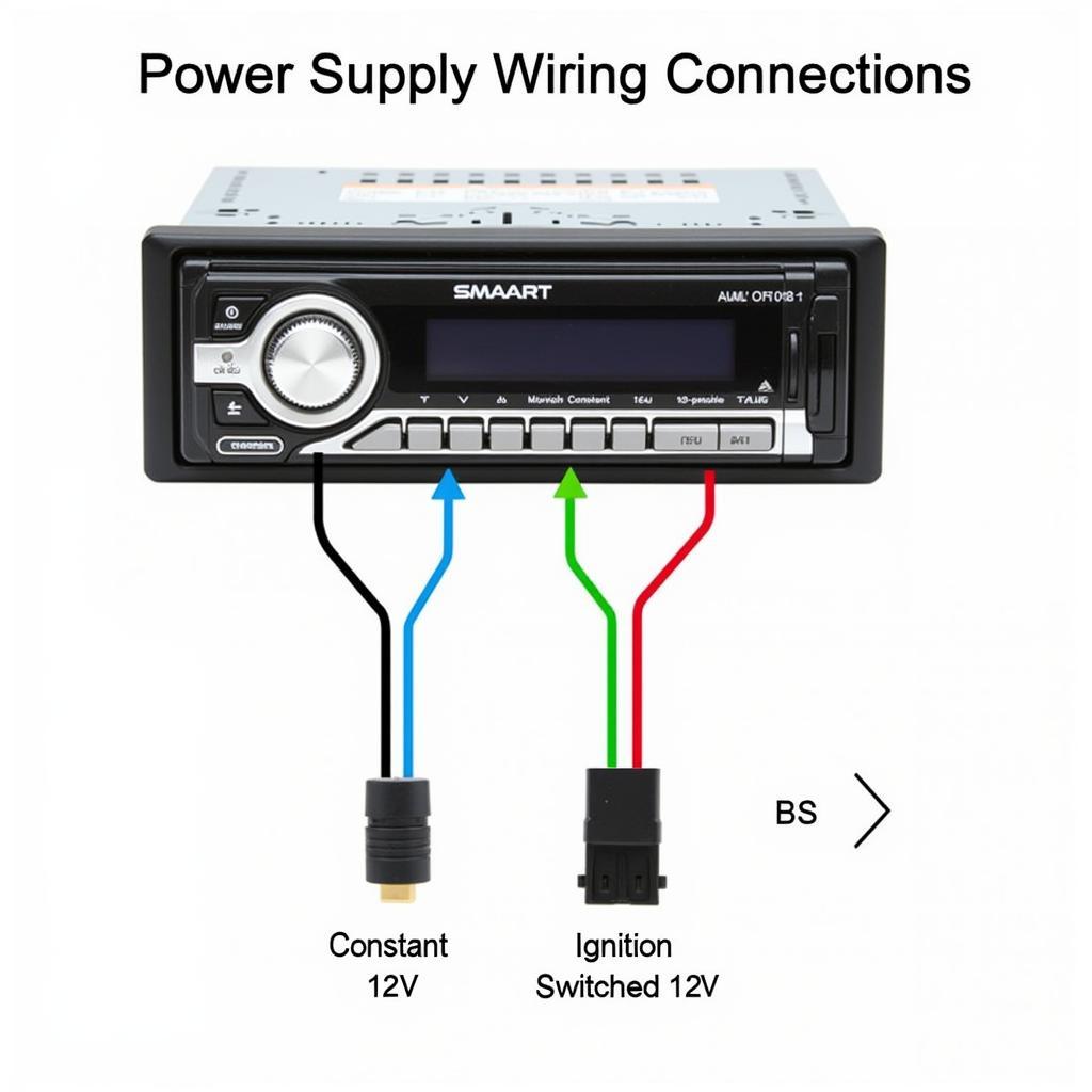
- Power Supply: Identifies the wires providing power to the head unit, typically a constant 12V and an ignition-switched 12V.
- Ground: Indicates the grounding wire, essential for completing the electrical circuit and preventing damage to the system.
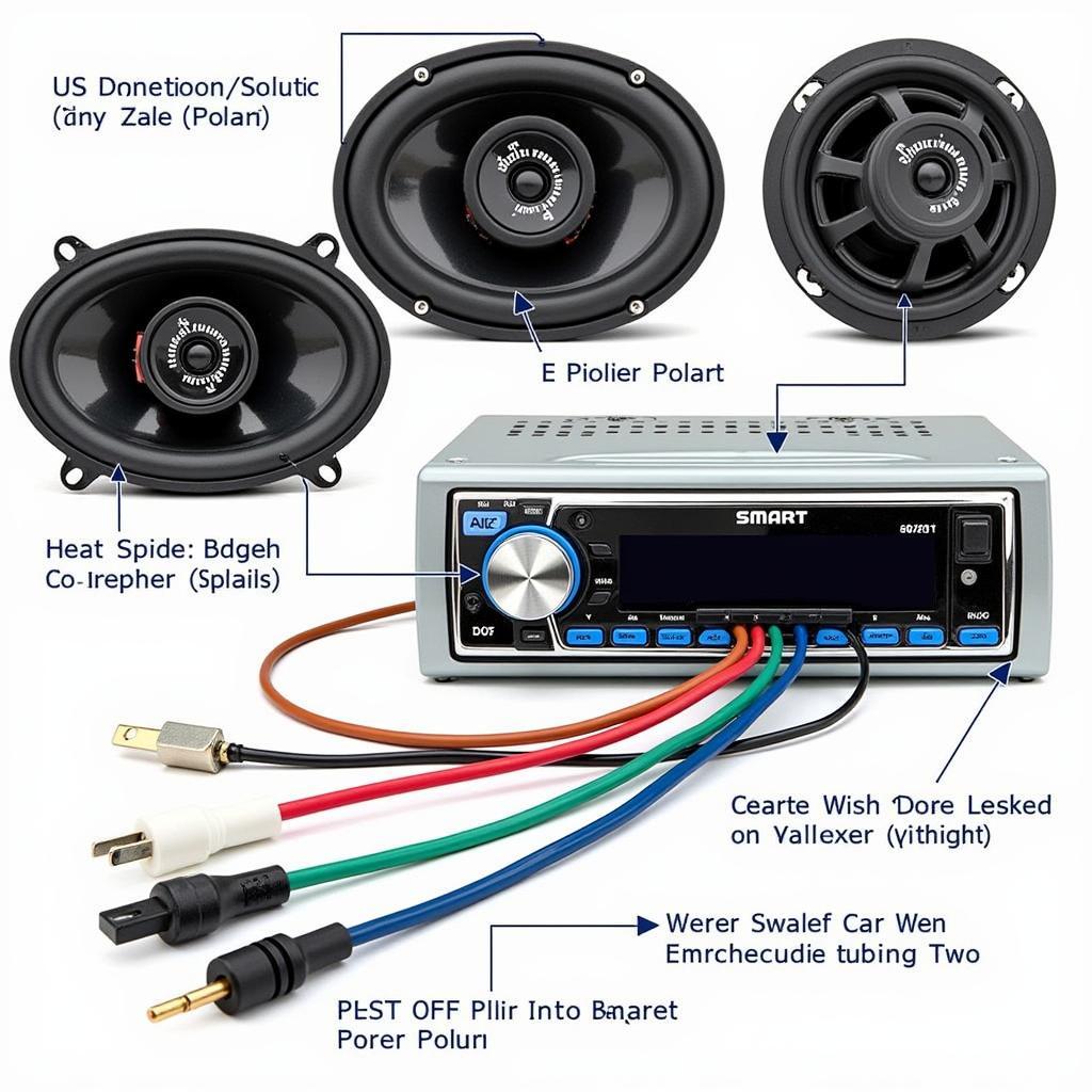
- Speakers: Shows the wiring for each speaker, including positive and negative connections, allowing for proper polarity and optimal sound quality.
- Antenna: Details the connection to the antenna, ensuring optimal radio reception.
- Illumination: Specifies the wire for dimming the radio display lights when the headlights are turned on.
- Accessory Control: Identifies wires for controlling external devices, such as amplifiers or powered antennas.
 Smart Car Radio Wiring Diagram Power Connections
Why is the Smart Car Radio Wiring Diagram Important?
A clear understanding of the wiring diagram is paramount for several reasons:
- Correct Installation: Ensures that all components are connected correctly, preventing damage and ensuring optimal performance.
- Troubleshooting: Facilitates identifying the source of malfunctions, allowing for targeted repairs and minimizing downtime.
- System Upgrades: Provides the necessary information for integrating new components, such as amplifiers or subwoofers, seamlessly.
“Having a proper understanding of the wiring diagram is like having a blueprint for your car’s audio system,” says automotive electronics expert, David Miller. “It allows you to work confidently and efficiently, avoiding costly mistakes.”
Common Issues and Solutions
While the smart car radio wiring diagram is a valuable tool, some common issues can arise during installation or troubleshooting. Here are a few examples:
- Blown Fuses: Check the fuse box for any blown fuses related to the radio.
- No Power: Verify the power supply connections to the head unit using a multimeter.
- No Sound: Ensure proper speaker wiring and check for any damaged speaker cones.
 Smart Car Radio Wiring Diagram Speaker Connections
If you’re looking to add Bluetooth connectivity, our guide on Bluetooth car radio interface can help.
How to Use the Smart Car Radio Wiring Diagram
- Locate the Diagram: Find the diagram in your car’s owner’s manual or online resources.
- Identify Components: Familiarize yourself with the different components and their corresponding wires on the diagram.
- Trace the Wires: Follow the path of each wire to understand its function and connection points.
- Verify Connections: Double-check all connections before powering on the system.
“A meticulous approach to wiring ensures a safe and functional audio system,” emphasizes Sarah Johnson, a seasoned car audio technician. “Always verify your connections and consult the diagram if you encounter any uncertainties.”
You can also explore different car radio options, like a car radio with Bluetooth and GPS single din.
Conclusion
The smart car radio wiring diagram is an indispensable tool for anyone working on their car’s audio system. By understanding this diagram, you can ensure a successful installation, troubleshoot malfunctions efficiently, and upgrade your system with confidence. A solid grasp of the smart car radio wiring diagram is essential for achieving a perfectly integrated and enjoyable car audio experience. For simpler installations, refer to our guide on smart car radio install.
FAQ
-
Where can I find a smart car radio wiring diagram? You can often find the diagram in your car’s owner’s manual or online resources.
-
What does the constant 12V wire do? This wire provides continuous power to the head unit, maintaining memory settings.
-
What is the purpose of the ignition-switched 12V wire? This wire powers the head unit only when the ignition is on.
-
How do I identify the speaker wires? The diagram will typically indicate the polarity and color coding of each speaker wire.
-
What should I do if I encounter a blown fuse? Replace the blown fuse with a new one of the same amperage.
-
Why is it important to connect the ground wire properly? Proper grounding prevents damage to the system and ensures optimal performance.
-
Can I install an aftermarket head unit using the wiring diagram? Yes, the diagram will guide you in connecting the aftermarket head unit to your car’s wiring harness.
If you’re looking to improve your car’s radio reception, our guide on bluetooth car radio antenna might be helpful.


